ISP Network System Design and Implementation
Scenario Description: ISP Network:
Goldfields Ltd. are UK based SME currently in the middle of a period of business growth and are planning to restructure their head office in Exeter. They are looking to totally remodel their network infrastructure including an “always on” private connection-based solution between each site and their datacentre in Exeter. They would like you to propose a new national network model. This restructure will see many of the staff relocated and an expansion to their head office datacentre. Currently, Internet access is provided via a basic ADSL connection, while stable currently they understand this requires replacement to allow for a stable service (including a nightly cross-site backup solution). Any provided proposal should be designed to facilitate potential future expansion and be designed in such a way to ensure flexibility, reliability and security.
Each new office building is roughly 180x80m and includes hot desk and meeting rooms for staff and visitors. The entire site requires high speed wireless access to guests and staff using BYOD systems, logically separated from the internal network. Therefore Goldfields require a full coverage WiFi floor plan before decorators are contracted and partition walls built.
As part of the security compliance concerns Goldfields wish to account for data in transit if failover requires them to utilise a series of site-to-site connections over a central VPN endpoint. To this end they have requested a routing path calculation for each site.
Offices:
• Exeter (Head Office)
- Devices: 35 Desktops, 35 IP Phones, 50-100 nomadic devices, Datacentre housing 8 servers
• Coventry
- Devices: 15 Desktops, 20 IP Phones, 20-50 nomadic devices
• York
- Devices: 10 Desktops, 10 IP Phones, 25-40 nomadic devices
• Northampton
- Devices: 15 Desktops, 15 IP Phones, 20-50 nomadic devices
• Liverpool
- Devices: 40 Desktops, 20 IP Phones, 10-50 nomadic devices
• Banbury
- Devices: 30 Desktops, 30 IP Phones, 50-100 nomadic devices
- Addressing Structure and Device Assignment tables
- Demonstration of modelled national network in Cisco Packet Tracer
- Demonstration of testing of the modelled network
- Reflection on specific hardware selection
- Presentation of 802.11 site coverage plan
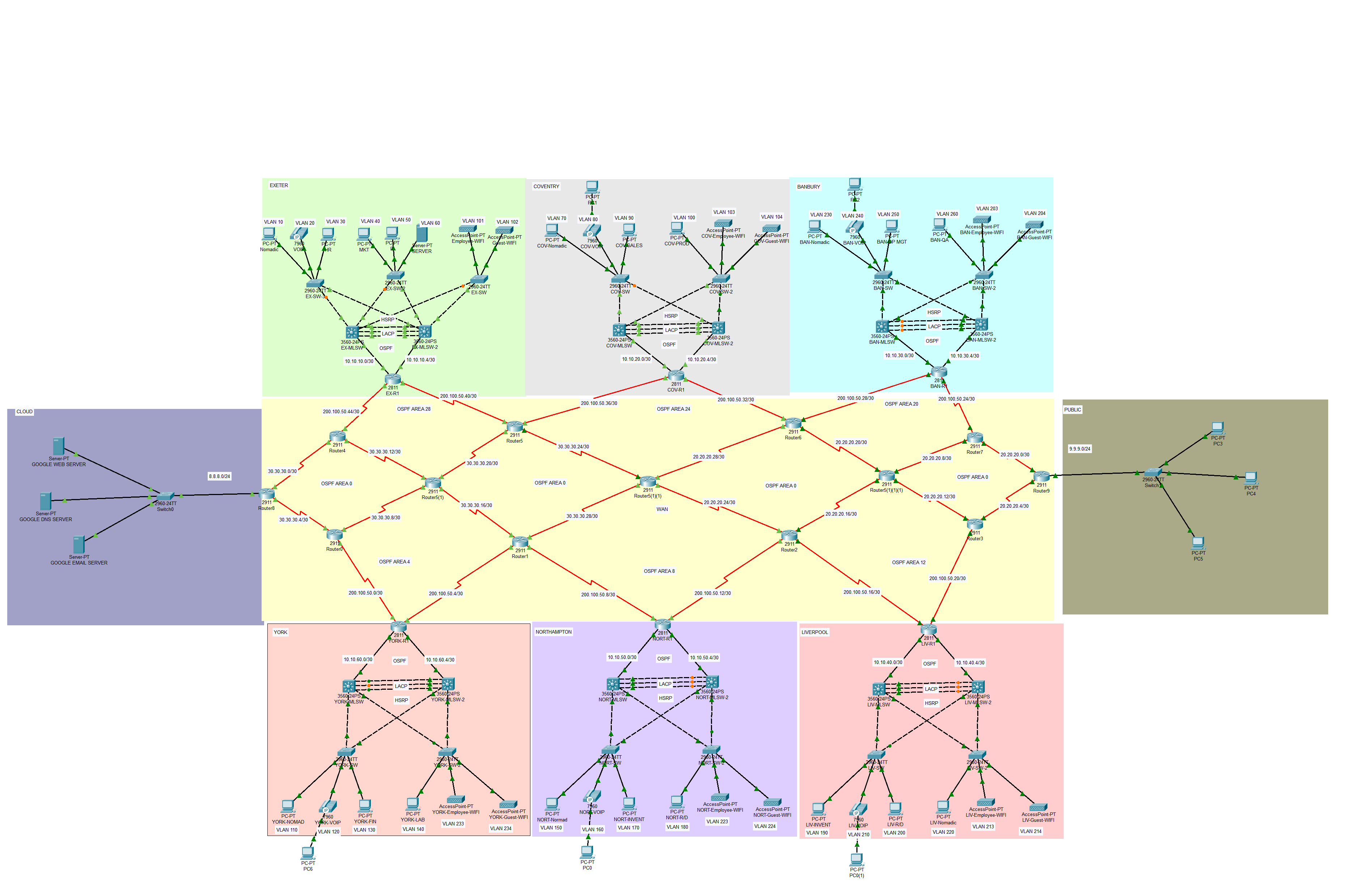
The network topology below satisfy the user requirements above and everything is verified, tested and working fine.
