Design and Implementation of a Secure Healthcare Network System (Project #11)
Project #11 Case Study and RequirementsDr. Devi ShettyLabs Limited is an Indian healthcare service provider specializing in diagnostic and related healthcare tests. Headquartered in Mumbai, the company conducts tests on blood, urine, and various human bodily tissues. It strategically employs information technology to digitize and securely access and market its services. The company's offices are located on the 35th, 36th, and 37th floors of the Great Namaste Towers. On the 35th floor, you'll find the Pharmacy and Medical Labs, serving approximately 200 users, along with the Reception and Guest Area accommodating around 1000 users. The 36th floor houses the Doctors and Consultancy department, catering to about 200 users, and also manages Procurement, HR, and Finance operations for 300 users. The 37th floor is divided between Internal Auditors and Corporate functions, involving around 120 users, and an entire IT team consisting of 300 users. The IT department is further structured into various teams, including Brand and Digital Marketing, IT Support, System/Network Admin, Network Security Engineers, Cybersecurity Analysts, Software Engineers, Cloud Engineers, and IT Management. Recognizing substantial growth potential, the company anticipates that the user count for each department will double by 2025, necessitating a focus on scalability during the design and implementation phases.
As an integral part of the company's ICT infrastructure, the following components have been incorporated:
- Internet Services Provider (ISP): The company has established a subscription with Airtel to ensure internet connectivity.
- Network Security: A Cisco ASA Firewall from the 5500-X series has been acquired to enhance network security.
- Network Routing: A Cisco WAN Router has been deployed to facilitate efficient data routing within the network. Note- For some reason, this router will be used for VoIP services.
- Switching Infrastructure: The network includes two Catalyst 3850 48-Port Switches, eight Catalyst 2960 48-Port Switches, and two Catalyst 2960 24-Port Switches to ensure robust local network connectivity.
- Server Hardware and Virtualization: Two HP ProLiant DL38 Gen10 servers will be utilized for virtualization through the VMWare ESXi hypervisor. They will host multiple virtual machines, including a Red Hat Directory Server responsible for managing user information in an LDAP-based directory. This server will handle DNS services and IPv4 address allocation for DHCP hosts. The two servers are used for fail-over purposes.
- Internal Servers: Internally hosted servers include a Health Information System, Email server, and File server, ensuring data accessibility and security.
- Storage: Two storage devices, NetApp product will be used to facilitate storage of resources.
- Voice and Wireless Infrastructure: Cisco Voice Gateways will be employed for VoIP and telephony services. Additionally, a Cisco Wireless LAN Controller (WLC) and ten Lightweight Access Points (LAPs) will centralize the management of the wireless network.
Due to security requirements, it has been decided that all LAN, WLAN, and VoIP users will be on a separate network segment within the same local area network. The firewall will be used to set security zones and filter traffic that moves in and out of the zones based on the configured inspection policies.
You have been hired as a network security engineer to design the network according to the requirements set by the senior management. You will consult an appropriate robust network design model to meet the design requirements. You are required to design and implement a secured, reliable, scalable, and robust network system that is paramount to safeguarding the Confidentiality, Integrity, and Availability of data and communication. The company places a strong emphasis on achieving top-tier performance, redundancy, scalability, and availability within its network infrastructure. As such, your task involves creating a comprehensive network design and executing its implementation. To facilitate this endeavor, the company has designated specific IP address ranges:
- WLAN: The WLAN network will operate within the IP address range of 10.10.0.0/16.
- LAN: For the local area network (LAN), the IP address range of 192.168.0.0/20 has been allocated.
- Voice: The Voice network will utilize the IP address range of 172.16.0.0/20.
- DMZ: The Demilitarized Zone (DMZ) will be assigned IP addresses from the range 10.20.20.0/26.
- Public Addresses: Public IP addresses from the range 197.200.100.0 have been allocated for externalfacing services, ensuring a visible and accessible presence on the internet.
- Design Tool: Utilize Cisco Packet Tracer for designing and implementing the network solution.
- Hierarchical Design: Implement a hierarchical model that incorporates redundancy for enhanced network resilience.
- ISPs: Establish connectivity to an Airtel ISP Router within the network infrastructure.
- WLC: Ensure that each department is equipped with a Wireless Access Point (WAP) to provide WiFi access to employees, corporate users, external auditors, and guests, all centrally managed by a Wireless LAN Controller (WLC).
- VoIP: Deploy IP phones in each department to support Voice over IP (VoIP) communication.
- VLAN: Maintain VLANs with the following IDs: 10 for LAN, 50 for WLAN, and 99 for VoIP across the entire network.
- EtherChannel: Implement the Link Aggregation Control Protocol (LACP) for EtherChannel configuration, enhancing link aggregation efficiency.
- STP PortFast and BPDUguard: Configure Spanning Tree Protocol (STP) PortFast and BPDUguard to expedite port transitions from blocking to forwarding states.
- Subnetting: Utilize subnetting techniques to allocate the appropriate number of IP addresses to each network group.
- Basic Settings: Configure fundamental device settings, including hostnames, and console passwords, enable passwords, banner messages, password encryption, and disable IP domain lookup.
- Inter-VLAN Routing: Enable devices in all departments to communicate with one another by configuring the respective multilayer switch for inter-VLAN routing.
- Core Switch: Assign IP addresses to Multilayer switches to enable both routing and switching functionalities.
- DHCP Server: Ensure that all devices in the network (excluding IP phones) obtain IP addresses dynamically from Active Directory (AD) servers located at the server farm site.
- Cisco 2811 Router: Deploy a Cisco Catalyst 2811 router capable of supporting telephony services.
- HSRP: Implement high-availability router protocols such as HSRP to achieve redundancy, load balancing, and failover capabilities.
- Static Addressing: Allocate static IP addresses to devices located in the server room.
- Telephony Service: Configure Voice over IP (VoIP) on the WAN router and assign dial numbers in the format (3...).
- Routing Protocol: Utilize Open Shortest Path First (OSPF) as the routing protocol to advertise routes on the firewall, routers, and multilayer switches.
- Standard ACL for SSH: Establish a simple standard Access Control List (ACL) on the VTY line to permit remote administrative tasks via SSH only for the Senior Network Security Engineer PC.
- Cisco ASA Firewall: Configure default static routes, basic settings, security levels, zones, and policies on the Cisco ASA Firewall to define access control and resource utilization within the network.
- Final Testing: Conduct thorough testing to verify proper communication and ensure that all configured elements function as intended.
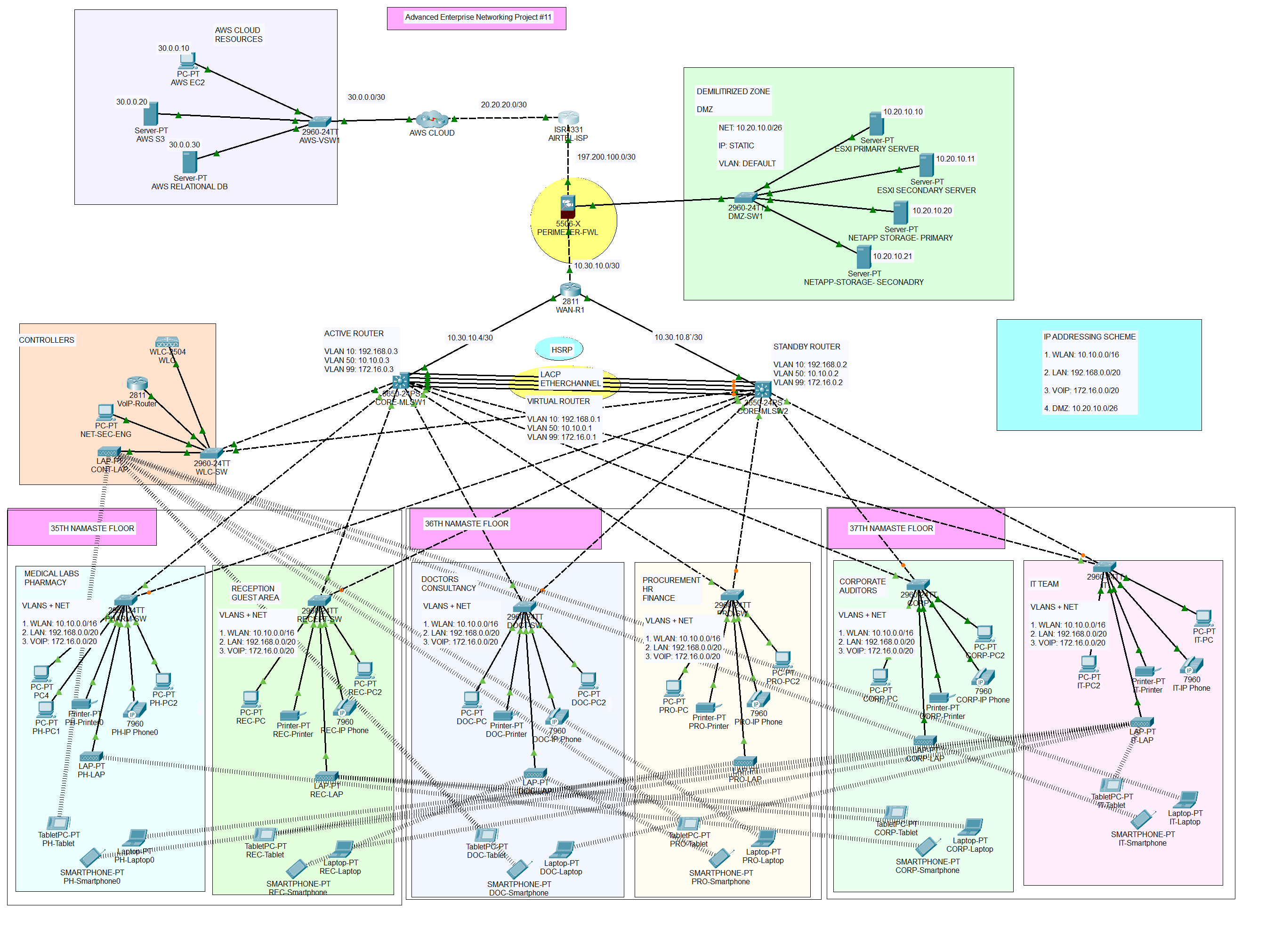
The network topology below satisfy the user requirements above and everything is verified, tested and working fine. You can get source file (Packet Tracer File) or watch on YouTube below.