Design and Implementation of a Secure Campus Area Network System (Project #12)
Project #12 Case Study and RequirementsMartin Luther King University stands as a prominent institution with a vast footprint, encompassing two campuses strategically positioned 100 miles apart within the United States. The university's organizational structure revolves around four key faculties: Health and Sciences, Business, Engineering/Computing, and Art/Design, both in the main and branch campuses. This diverse array of faculties accommodates the dynamic needs of both students and staff, fostering a rich academic environment. To ensure seamless connectivity and technological cohesion, an integral component of the university is its Information Technology (IT) department situated at the main campus. This central hub orchestrates the management of both campuses, overseeing the intricate network that binds them together. Currently, the university caters to a substantial community, boasting a collective headcount of approximately 30,000 users spread across the two campuses. In anticipation of significant growth on the horizon, the university envisions a doubling of user counts within each department by the year 2025. This foresight underscores the necessity for a robust and scalable infrastructure, prompting a strategic emphasis on scalability throughout the design and implementation phases.
At the heart of the technological infrastructure lies the main campus, which hosts a server farm, often referred to as the Demilitarized Zone (DMZ). Within this fortified zone, essential servers such as DHCP, DNS, FTP, WEB, Email, and SMTP are strategically housed. Recognizing the importance of secure resource access, users at the branch campus are equipped with the capability to securely connect to and utilize these centralized servers. This safeguarded connectivity ensures that educational, informational, and communication resources are readily available to all users, irrespective of their physical location.
As an integral part of the University's ICT infrastructure, the following components have been incorporated:
- Internet Services Provider (ISP): The company has established a subscription with Airtel to ensure internet connectivity.
- Network Security: Two Cisco ASA Firewalls from the 5500-X series have been acquired to enhance network security. Each campus will have its firewall but the main campus will contain the DMZ or the server farm.
- Network Routing: Both the firewalls and the core switches will be used instead of a router.
- Switching Infrastructure: The network includes two Catalyst 3850 48-Port Switches for each campus, and Catalyst 2960 48-Port Switches per faculty to ensure robust local network connectivity.
- Server Hardware and Virtualization: Two physical servers will be utilized for virtualization through the hypervisor to achieve multiple virtual machines for various services. For redundancy or failover, we will have two DHCP servers running at the same time..
- Wireless Infrastructure: Two Cisco Wireless LAN Controllers (WLC) and various Lightweight Access Points (LAPs) will centralize the management of the wireless network.
- Site-to-site IPsec VPN: Configure IPsec VPN on the two firewalls to enable secure communication between the main and the branch campus.
Due to security requirements, it has been decided that all LAN and WLAN users will be on a separate network segment within the same local area network. The firewall will be used to set security zones and filter traffic that moves in and out of the zones based on the configured inspection policies. Finally, the two campuses should have a secure tunnel of communication via an IPsec VPN.
You have been hired as a network security engineer to design the network according to the requirements set by the senior management. You will consult an appropriate robust network design model to meet the design requirements. You are required to design and implement a secured, reliable, scalable, and robust network system that is paramount to safeguarding the Confidentiality, Integrity, and Availability of data and communication. The University places a strong emphasis on achieving top-tier performance, redundancy, scalability, and availability within its network infrastructure. As such, your task involves creating a comprehensive network design and executing its implementation. To facilitate this endeavor, the University has designated specific IP address ranges:
- WLAN: For the management, the IP address range of 192.168.10.0/24 has been allocated.
- LAN: The WLAN network will operate within the IP address range of 10.10.0.0/16 for the main campus and 10.11.0.0/16 for the branch campus.
- Voice: For the local area network (LAN), the IP address range of 172.16.0.0/16 for the main campus and 172.17.0.0/16 for the branch campus.
- DMZ: The Demilitarized Zone (DMZ) will be assigned IP addresses from the range 10.20.20.0/27.
- Public Addresses: Public IP addresses from the range 105.100.50.0/30 for the main campus and 205.200.100.0/30 for the branch campus.
- Design Tool: Utilize Cisco Packet Tracer for designing and implementing the network solution.
- Hierarchical Design: Implement a hierarchical model that incorporates redundancy for enhanced network resilience.
- ISPs: Establish connectivity to an Airtel ISP Router within the network infrastructure.
- WLC: Ensure that each department is equipped with a Wireless Access Point (WAP) to provide WiFi access to employees, corporate users, external auditors, and guests, all centrally managed by a Wireless LAN Controller (WLC).
- VoIP: Deploy IP phones in each department to support Voice over IP (VoIP) communication.
- VLAN: Maintain VLANs with the following IDs: 10 for Management, 20 for LAN, 50 for WLAN, and finally, 199 for Blackhole in which all unused ports are placed.
- EtherChannel: Implement the Link Aggregation Control Protocol (LACP) for EtherChannel configuration, enhancing link aggregation efficiency.
- STP PortFast and BPDUguard: Configure Spanning Tree Protocol (STP) PortFast and BPDUguard to expedite port transitions from blocking to forwarding states.
- Subnetting: Utilize subnetting techniques to allocate the appropriate number of IP addresses to each network group.
- Basic Settings: Configure fundamental device settings, including hostnames, and console passwords, enable passwords, banner messages, password encryption, and disable IP domain lookup.
- Inter-VLAN Routing: Enable devices in all departments to communicate with one another by configuring the respective multilayer switch for inter-VLAN routing.
- Core Switch: Assign IP addresses to Multilayer switches to enable both routing and switching functionalities.
- DHCP Server: Ensure that all devices in the network obtain IP addresses dynamically from Active Directory (AD) servers located at the server farm site.
- HSRP: Implement high-availability router protocols such as HSRP to achieve redundancy, load balancing, and failover capabilities.
- Static Addressing: Allocate static IP addresses to devices located in the server room.
- Routing Protocol: Utilize Open Shortest Path First (OSPF) as the routing protocol to advertise routes on the firewall, routers, and multilayer switches.
- Standard ACL for SSH: Establish a simple standard Access Control List (ACL) on the VTY line to permit remote administrative tasks via SSH only for the Senior Network Security Engineer PC.
- Cisco ASA Firewall: Configure default static routes, basic settings, security levels, zones, and policies on the Cisco ASA Firewall to define access control and resource utilization within the network.
- Site-to-site IPsec VPN on Cisco ASA Firewall: Configure Site-to-site IPsec VPN between the two firewalls to enable secure communication between HQ and branch campus.
- Final Testing: Conduct thorough testing to verify proper communication and ensure that all configured elements function as intended.
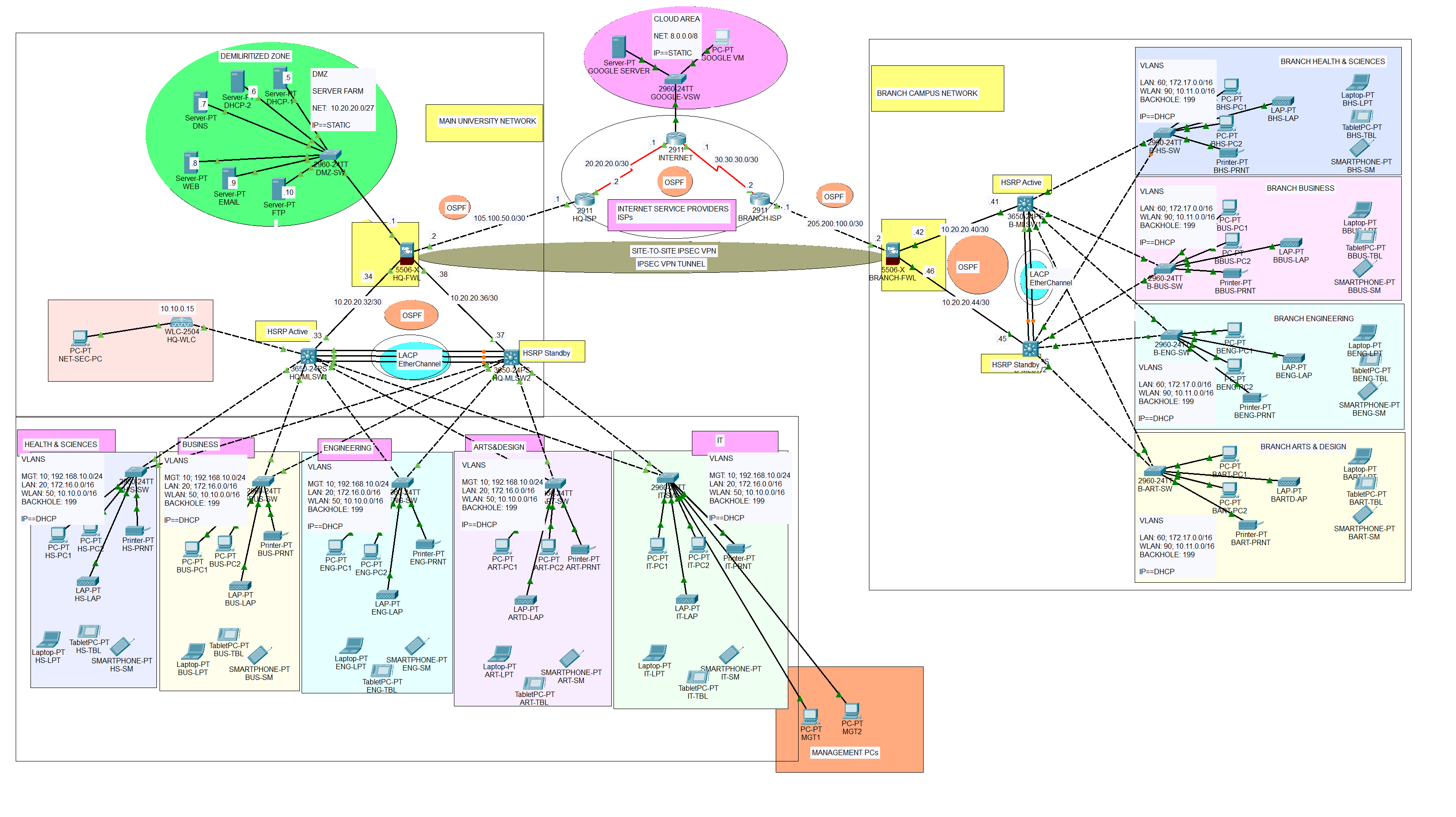
The network topology below satisfy the user requirements above and everything is verified, tested and working fine. You can get source file (Packet Tracer File) or watch on YouTube below.