Design and Implementation of a Secure Company Network System (Project #13)
Project #13 Case Study and RequirementsCytonn Innovation Ltd is a dynamic and forward-thinking company specializing in providing innovative cloud solutions to clients worldwide. Leveraging cutting-edge technology and a team of highly skilled professionals, Cytonn Innovation focuses on developing and implementing cloud-based solutions tailored to meet the evolving needs of businesses across various industries. With a strong emphasis on creativity, agility, and customercentricity, Cytonn Innovation aims to empower organizations to enhance their operational efficiency, scalability, and competitiveness in today's digital landscape.
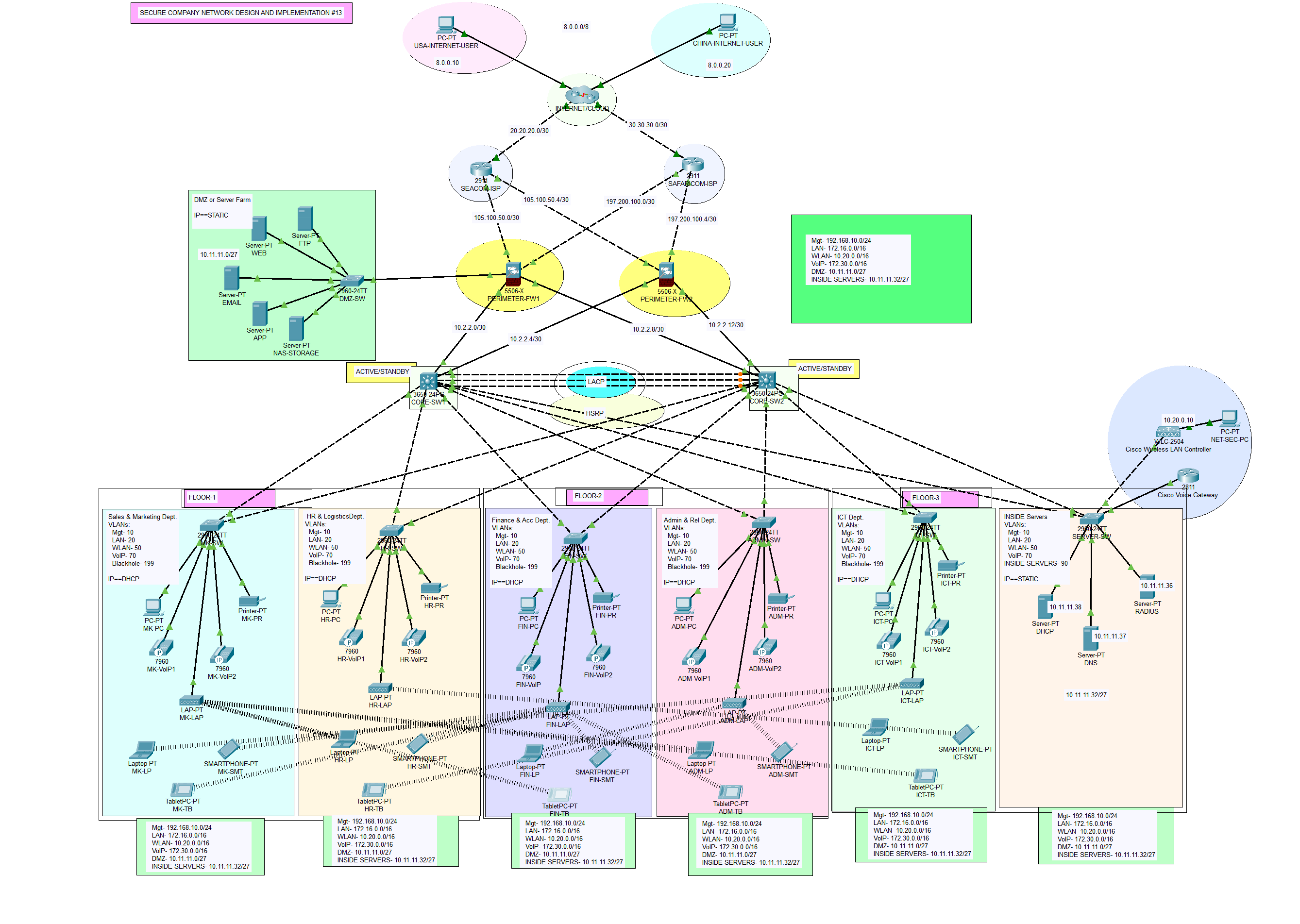
With a workforce of 600 staff, Cytonn Innovation Ltd recently expanded and is preparing to move to a new building. The new building, comprising three floors, will house various departments, including Sales and Marketing, Human Resources and Logistics, Finance and Accounts, Administrator and Public Relations, ICT, and a Server Room. The ICT department further hosts Software Developers, Cloud Engineers, Cybersecurity Engineers, Network Engineers, System Administrators, IT Support Specialists, Business Analysts and Project Managers.
Prior to the move, a new network service needs to be designed and implemented in the new building. To ensure robust security, Cytonn Innovation will implement several security measures to protect the network from internal and external threats. The firewall will have outside, inside, and DMZ security zones, with essential servers strategically housed within the fortified zone. Additionally, Active Directory (AD) servers, responsible for managing and authenticating users, computers, and resources within the internal network, will be placed on the Inside zone of the firewall- this implies that servers such as DHCP, DNS, and Radius will all be on the inside zone, while other servers such as FTP, WEB, Email, APP, and NAS storage will be located in the DMZ- the zone can be attached to any firewall as of now. This meticulous planning and deployment of security measures will safeguard the network and ensure smooth operations for Cytonn Innovation Ltd in its new building.
At the heart of the technological infrastructure lies the main campus, which hosts a server farm, often referred to as the Demilitarized Zone (DMZ). Within this fortified zone, essential servers such as DHCP, DNS, FTP, WEB, Email, and SMTP are strategically housed. Recognizing the importance of secure resource access, users at the branch campus are equipped with the capability to securely connect to and utilize these centralized servers. This safeguarded connectivity ensures that educational, informational, and communication resources are readily available to all users, irrespective of their physical location.
As an integral part of the University's ICT infrastructure, the following components have been incorporated:
- Internet Services Provider (ISP): The Company has established a subscription with two ISPs (SEACOM & Safaricom) to ensure redundant internet connectivity.
- Network Security: Two Cisco ASA Firewalls from the 5500-X series have been acquired to enhance network security and redundancy.
- Network Routing: Both the firewalls and the core switches will be used instead of a router.
- Switching Infrastructure: The network includes two Catalyst 3850 48-Port Switches for each campus, and Catalyst 2960 48-Port Switches to ensure robust local network connectivity.
- Server Hardware and Virtualization: Two physical servers will be utilized for virtualization through the hypervisor to achieve multiple virtual machines for various services. For redundancy or failover, we will have two DHCP servers running at the same time..
- Wireless Infrastructure: Two Cisco Wireless LAN Controllers (WLC) and various Lightweight Access Points (LAPs) will centralize the management of the wireless network.
- VoIP or IP Phones: A Cisco Voice Gateway will be used to enable telephony service in the network.
Therefore, as a key member of the Networks Team, you have been tasked to design a network for the new building. At this stage, logical design is required, which shows the measures that you would put in place to ensure that the new network meets the current business need and is future-proofed. The company places a strong emphasis on achieving top-tier performance, redundancy, scalability, and availability within its network infrastructure. As such, your task involves creating a comprehensive network design and executing its implementation. To facilitate this endeavor, the Company has designated specific IP address ranges:
- Management Network: For the management, the IP address range of 192.168.10.0/24 has been allocated.
- WLAN: The WLAN network will operate within the IP address range of 10.20.0.0/16.
- LAN: For the local area network (LAN), the IP address range of 172.16.0.0/16.
- VoIP: For the local area network (LAN), the IP address range of 172.30.0.0/16.
- DMZ: The Demilitarized Zone (DMZ) will be assigned IP addresses from the range 10.11.11.0/27.
- Public Addresses: Public IP addresses from the range 105.100.50.0/30 from SEACOM and 197.200.100.0/30 from Safaricom.
- Design Tool: Utilize Cisco Packet Tracer for designing and implementing the network solution.
- Hierarchical Design: Implement a hierarchical model that incorporates redundancy for enhanced network resilience.
- ISPs: Establish connectivity to an Airtel ISP Router within the network infrastructure.
- WLC: Ensure that each department is equipped with a Wireless Access Point (WAP) to provide WiFi access to employees, corporate users, external auditors, and guests, all centrally managed by a Wireless LAN Controller (WLC).
- VoIP: Deploy IP phones in each department to support Voice over IP (VoIP) communication.
- VLAN: Maintain VLANs with the following IDs: 10 for Management, 20 for LAN, 50 for WLAN, 70 for VoIP, and finally, 199 for Blackhole in which all unused ports are placed.
- EtherChannel: Implement the Link Aggregation Control Protocol (LACP) for EtherChannel configuration, enhancing link aggregation efficiency.
- STP PortFast and BPDUguard: Configure Spanning Tree Protocol (STP) PortFast and BPDUguard to expedite port transitions from blocking to forwarding states.
- Subnetting: Utilize subnetting techniques to allocate the appropriate number of IP addresses to each network group.
- Basic Settings: Configure fundamental device settings, including hostnames, and console passwords, enable passwords, banner messages, password encryption, and disable IP domain lookup.
- Inter-VLAN Routing: Enable devices in all departments to communicate with one another by configuring the respective multilayer switch for inter-VLAN routing.
- Core Switch: Assign IP addresses to Multilayer switches to enable both routing and switching functionalities.
- DHCP Server: Ensure that all devices in the network obtain IP addresses dynamically from the servers located at the server farm site.
- HSRP: Implement high-availability router protocols such as HSRP to achieve redundancy, load balancing, and failover capabilities.
- Static Addressing: Allocate static IP addresses to devices located in the server room.
- Routing Protocol: Utilize Open Shortest Path First (OSPF) as the routing protocol to advertise routes on the firewall, routers, and multilayer switches.
- Standard ACL for SSH: Establish a simple standard Access Control List (ACL) on the VTY line to permit remote administrative tasks via SSH only for the Senior Network Security Engineer PC.
- Cisco ASA Firewall: Configure default static routes, basic settings, security levels, zones, and policies on the Cisco ASA Firewall to define access control and resource utilization within the network.
- Final Testing: Conduct thorough testing to verify proper communication and ensure that all configured elements function as intended.
The network topology below satisfy the user requirements above and everything is verified, tested and working fine. You can get source file (Packet Tracer File) or watch on YouTube below.