Design and Implementation of an Hotel System Network Design (Project #3)
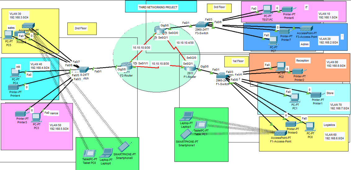
Project #3 Case Study and RequirementsAs a part of your end year networking project, you are required to design and implement Vic Modern Hotel network. The hotel has three floors; in the first floor there three departments (Reception, store and Logistics), in the second floor there are three departments (Finance, HR and Sales/Marketing), while the third floor hosts the IT and Admin. Therefore, the following are part of the considerations during the design and implementation;
- There should be three routers connecting each floor (all placed in the server room in IT department).
- All routers should be connected to each other using serial DCE cable.
- The network between the routers should be 10.10.10.0/30,10.10.10.4/30 and 10.10.10.8/30.
- Each floor is expected to have one switch (placed in the respective floor).
- Each floor is expected to have WIFI networks connected to laptops and phones.
- Each department is expected to have a printer.
- Each department is expected to be in different VLAN with the following details;
1st Floor;
- Reception- VLAN 80, Network of 192.168.8.0/24
- Store- VLAN 70, Network of 192.168.7.0/24
- Logistics- VLAN 60, Network of 192.168.6.0/24
2nd Floor;
- Finance- VLAN 50, Network of 192.168.5.0/24
- HR- VLAN 40, Network of 192.168.4.0/24
- Sales- VLAN 30, Network of 192.168.3.0/24
3rd Floor;
- Admin- VLAN 20, Network of 192.168.2.0/24
- IT- VLAN 10, Network of 192.168.1.0/24 - Use OSPF as the routing protocol to advertise routes.
- All devices in the network are expected to obtain IP address dynamically with their respective router configured as the DHCP server.
- All the devices in the network are expected to communicate with each other.
- Configure SSH in all the routers for remote login.
- In IT department, add PC called Test-PC to port fa0/1 and use it to test remote login.
- Configure port security to IT-dept switch to allow only Test-PC to access port fa0/1 (use sticky method to obtain mac-address with violation mode of shutdown.)
- Creating a network topology using Cisco Packet Tracer.
- Hierarchical Network Design.
- Connecting Networking devices with Correct cabling.
- Creating VLANs and assigning ports VLAN numbers.
- Subnetting and IP Addressing.
- Configuring Inter-VLAN Routing (Router on a stick).
- Configuring DHCP Server (Router as the DHCP Server).
- Configuring SSH for secure Remote access.
- Configuring switchport security or Port-Security on the switches.
- Configuring WLAN or wireless network (Cisco Access Point).
- Host Device Configurations.
- Test and Verifying Network Communication.
The network topology below satisfy the user requirements above and everything is verified, tested and working fine. You can get source file (Packet Tracer File) or watch on YouTube below.