Design and Implementation of a Bank System Network Design (Project #5)
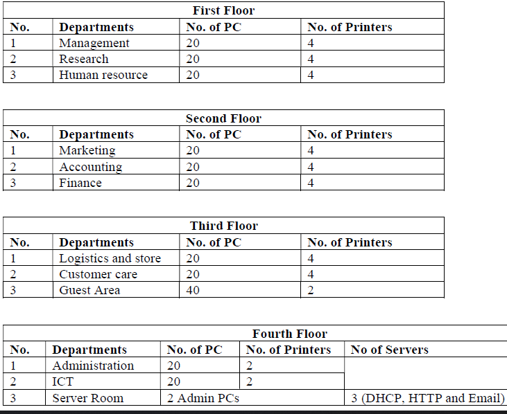
Project #5 Case Study and RequirementsRadeon Company Ltd. is a US-owned company that deals with Banking and Insurance. The company is intending to expand its services across the African continent having the first branch to be located in Nairobi, Kenya. The company has secured a four-story building to operate within the Kenyan capital city. Therefore, the company would like to allow sourcing the knowledge from a group of final-year students from the local university to design and implement their company network. Assume you are among the students to take over this role, carefully read down the requirements then model the design and implement the network based on the company's needs. Each floor has departments as provided in the table below.;
- Use a software modeling tool to visualize the network topology (Use Hierarchical Network Design
- Software Modelling Tools: MS Visio, Visual Paradigm, or Draw.io for modeling network design. - Use any of the following network simulation software to implement the above topology.
- Simulation software: Cisco Packet tracer or GNS3 for design and implementation. - Use OSPF as the routing protocol to advertise routes.
- Each department is required to have a wireless network for the users.
- Each department except the server room will be anticipated to have around 60 users both wired and wireless users.
- Host devices in the network are required to obtain IPv4 addresses automatically.
- Devices in all the departments are required to communicate with each other.
- Create HTTP, and E-mail servers.
- All devices in the network are expected to obtain an IP address dynamically from the dedicated DHCP servers located at the server room.
- Configure SSH in all the routers for remote login.
- Configure the basic configuration of the devices: Hostnames, Line Console and Enable passwords, Banner messages Disable domain IP lookup, encrypt all configured passwords.
- Each department should be in a different VLAN and subnetwork; VLANs you will use in your case, e.g. 10, 20, 30… etc..
- Planning of IP Addresses: You have been given 192.168.10.0 as the base address for this network. Do subnetting based on the number of hosts in every department as provided above. Identify subnet mask, useable IP address range, and broadcast address for each subnet.
- End Device Configurations: Configure all the end devices in the network with the appropriate IP address based on the calculations above.
- Configure port-security: Use sticky command to obtain MAC Address and Violation mode of the shutdown.
- Test and Verifying Network Communication.
- Creating a network topology using Cisco Packet Tracer.
- Hierarchical Network Design.
- Connecting Networking devices with Correct cabling.
- Configuring Basic device settings.
- Creating VLANs and assigning ports VLAN numbers.
- Subnetting and IP Addressing.
- Configuring Inter-VLAN Routing on the Multilayer switches (Switch Virtual Interface).
- Configuring Dedicated DHCP Server device to provide dynamic IP allocation.
- Configuring SSH for secure Remote access.
- Configuring OSPF as the routing protocol.
- Configuring switchport security or Port-Security on the switches.
- Configuring WLAN or wireless network (Cisco Access Point).
- Host Device Configurations.
- Test and Verifying Network Communication.
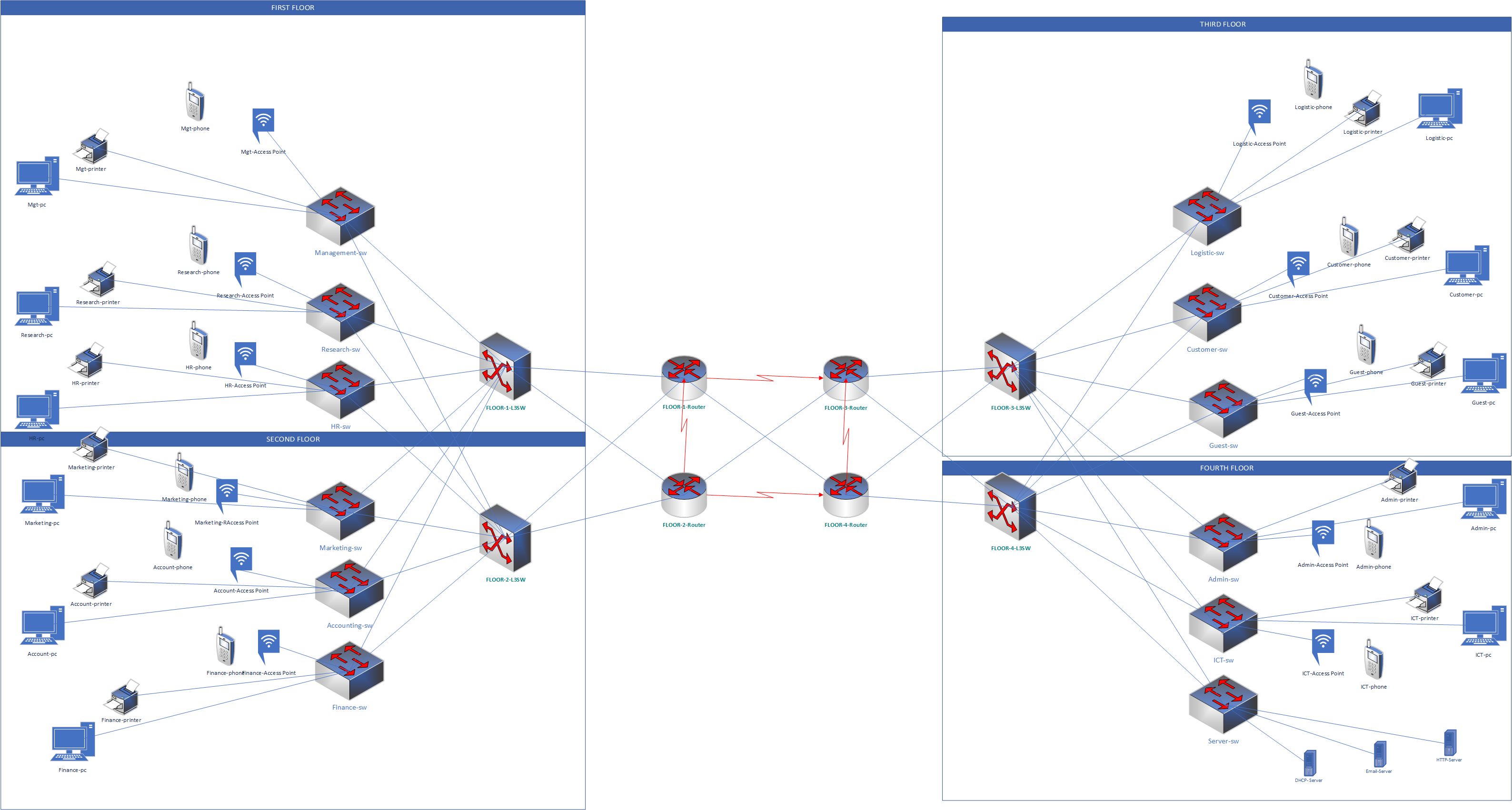
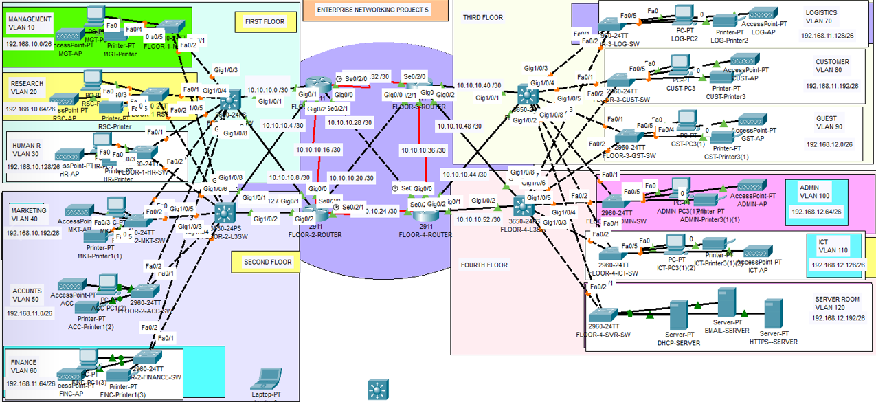
The network topology below satisfy the user requirements above and everything is verified, tested and working fine. You can get source file (Packet Tracer File) or watch on YouTube below.