Design and Implementation of a VoIP- IP Telephony System Network Design (Project #8)
Project #8 Case Study and RequirementsTurtle Consultancy Limited specialised in delivering IT infrastructure solutions to mediumsized organizations worldwide. With the expansion of the company, a newly acquired branch needs a network. Your manager is faced with the demands of business and a plethora of technology challenges.
You have been recently hired as a Network Engineer and assigned the task of designing and implementing a VoIP network that is based on the requirements and specifications outlined by your manager.
All desktops have an associated telephone set (each PC is connecting directly to a Phone, not a switch). The network consists of four servers (DHCP, EMAIL, DNS,HTTP) located at the server side site and is fully configured for the operations, and all servers are shared between all users.
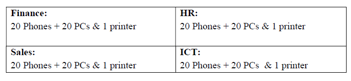
Each group has been assigned the task of designing, and implementing a network infrastructure for Turtle Consultancy Limited by internetworking three departments which are as follows:;
The IT Manager emphasized scalability and availability, and hence you are required to provide a complete network infrastructure design and implementation. Turtle Consultancy Limited will be using the following IP address: 192.168.100.0/24 for Data, 172.16.100.0/24 for Voice, and 10.10.10.0/24 between the routers.
- Design a networked system to meet the given specifications. Use packet tracer software to design your network.
- Routers- Each department is to have VoIP enabled router with server-side LAN attached to the ICT department router. Note: use Cisco 2811 router.
- Switches- Each department has an access layer switch. Note: use Cisco 2960 switch.
- Connections- Use serial connections between a router and a router, then a straightthrough cable between the router to switch, switch to hosts, phones to PCs.
- Subnets- Each department will be accessing two subnetworks, for example, data and voice subnets. Note: carry out appropriate subnetting.
- Basic settings- Configure basic device settings such as hostnames, console passwords, enable passwords, banner messages, encrypt all passwords, and disable IP domain lookup.
- DHCP Server- For voice (VoIP), use the respective router as the DHCP server while for Data use the DHCP server device at the server-side site.
- VLANs- Each department will be in two VLANS. One for data and another for voice. Note: All IP phones in the network should be in VLAN 100.
- Inter-VLAN Routing- Use router-on-a-stick to enable inter-VLAN routing on the network. Note: create subinterfaces for both data and voice VLANs.
- IP Addressing- All devices in the network are expected to obtain an IP address dynamically from the respective DHCP servers while the devices in the server room are to be allocated IP addresses statically.
- Routing protocol- Use OSPF as the routing protocol to advertise routes on the routers.
- Remote Access- Configure SSH in all the routers for remote login.
- Telephony service- Configure VoIP on the routers and allocate dial numbers in this format for the departments, Finance(1..), HR (2..), Sales (3..), and ICT (4..), (where 1.. can be 101 to 199) and so on.
- Routing for VoIP- Configure dial-peering on the routers to allow IP phones from different routers to communicate.
- Finalize- Test Communication, ensure everything configured is working as expected.
- Creating a network topology using Cisco Packet Tracer.
- Hierarchical Network Design.
- Connecting Networking devices with Correct cabling.
- Configuring Basic device settings.
- Creating VLANs and assigning ports VLAN numbers.
- Creating both data and voice VLANs and assigning ports VLAN numbers.
- Subnetting and IP Addressing.
- Configuring Inter-VLAN Routing on the Routers (router-on-a-stick).
- Configuring Dedicated DHCP Server device for Data to provide dynamic IP allocation.
- Configuring Routers as DHCP server for Voice to provide IP Phones dynamic IP allocation.
- Configuring SSH for secure Remote access.
- Configuring OSPF as the routing protocol.
- Configuring VoIP or Telephony service configuration in all routers.
- Configuring Routing for VoIP or Dial peering configuration in all routers.
- Host Device Configurations.
- Test and Verifying Network Communication.
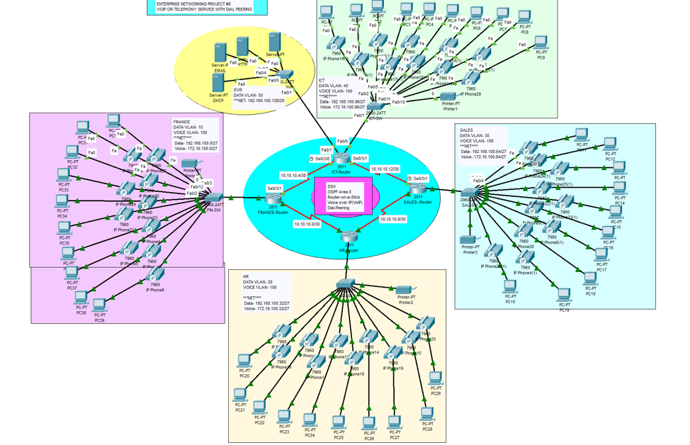
The network topology below satisfy the user requirements above and everything is verified, tested and working fine. You can get source file (Packet Tracer File) or watch on YouTube below.